
The Hi-Tec Range of VHF yagis and folded dipoles spans a Commercial and Professional series.
VHF folded dipoles can also be provided in multiple Stacked arrays.
| Bands available | Frequency range |
| A Band | 80-88 MHz |
| FM Broadcast | 88-108 MHz |
| Aviation Band | 115-136 MHz |
| ESB Band | 138-144 MHz |
| E Band | 150-156 MHz |
| VHF Marine Band | 156-162 MHz |
| EE Band | 162-174 MHz |
| Spot frequencies on request. |
VHF FOLDED DIPOLES & YAGIS – COMMERCIAL SERIES
The Hi-Tec Commercial Range of VHF yagis and folded dipoles are designed for urban site installations. Being lightweight with a small projected surface area, they can be installed on low cost supports. The coding “FD” indicates a folded dipole and “Y” indicates a yagi.
Commercial series antennas are constructed from Grade 6000 series aluminium and corrosion resistance is increased by a silver anodised finish. Elements are 12mm x 1.4mm extruded sections, which provides a robust antenna.

The boom section is 25mm x 25mm x 1.7mm square tube, to which the elements are clamped. This system allows the aerial to be shipped knocked down as a kitset. Cast aluminium clamps with stainless steel hardware are used to mount each element to the boom.
Models CFD & CY Series.
The nominal feed impedance is 50 Ohms with the matching section sealed within the driven element, eliminating the need for an external balun. A 1m tail of RG58 coax is fitted as standard.
Mounting for vertical polarisation is standard with the clamp usually located at the rear of the boom. There are four mounting options available for clamping to 25mm, 38mm, 48mm or 63mm outside diameters, with the 25mm clamp supplied as standard. As an alternative the Universal Clamp (CLUV) clamp may be used. This provides flexibility in mounting to either vertical or horizontal polarisation.
Range 80 – 90MhZ
CFDA
CY2A
CY3A
CY4A
Frequency range (MHz)
80 – 90
Number of elements
1
2
3
4
Bandwidth (MHz)
10
8
2
2
Gain (dBd)
0
3
6
7.5
Half Power Beamwidth E Plane (deg)
N/A
65
63
58
Half Power Beamwidth H Plane (deg)
N/A
105
96
81
Front to back ratio (dB)
0
10
10
12
Input impedance (Ohms)
50
Return loss (dB & VSWR)
<-14dB 1.5:1
Maximum power (W)
200
Cable type and length
RG58, 1 Metre
Boom diameter (mm)
25 square
Max element length (m)
1.6
1.8
Boom length (m)
1
1.5
2.2
Projected area (M2)
0.07
0.09
0.13
0.17
Weight (kg)
0.5
0.6
0.8
1.0
Mounting location
Rear
Range 110 – 170MhZ (1-3)
CFDE
CY2E
CY3E
Frequency range (MHz)
110 – 170
Number of elements
1
2
3
Bandwidth (MHz)
20
15
8
Gain (dBd)
0
3
5.5
Half Power Beamwidth E Plane (deg)
N/A
70
62
Half Power Beamwidth H Plane (deg)
N/A
145
95
Front to back ratio (dB)
0
10
13
Input impedance (Ohms)
50
Return loss (dB & VSWR)
<-14dB 1.5:1
Maximum power (W)
200
Cable type and length
RG58, 1 Metre
Max element length (m)
1
1
1.1
Boom length (m)
0.8
0.8
1
Boom diameter (mm)
25 square
Projected area (M2)
0.04
0.06
0.08
Weight (kg)
0.5
0.6
0.8
Mounting location
Rear
Range 110 – 170MhZ (4-6)
CY4E
CY5E
CY6E
Frequency range (MHz)
110 – 170
Number of elements
4
5
6
Bandwidth (MHz)
8
Gain (dBd)
7
8
9
Half Power Beamwidth E Plane (deg)
58
58
56
Half Power Beamwidth H Plane (deg)
74
68
65
Front to back ratio (dB)
15
Input impedance (Ohms)
50
Return loss (dB & VSWR)
<-14dB 1.5:1
Maximum power (W)
200
Cable type and length
RG58, 1 Metre
Max element length (m)
1.1
Boom diameter (mm)
25 square
Boom length (m)
1.3
1.6
2.3
Projected area (M2)
0.1
0.12
0.14
Weight (kg)
1.0
1.2
1.3
Mounting location
Rear
Centre

VHF FOLDED DIPOLES – PROFESSIONAL SERIES
This range of folded dipoles provides broadband unity gain and is designed for general purpose base station and repeater sites. All models have vertically polarised radiation patterns which can be offset by locating the dipole at specific distances from a metallic support structure or by using a reflector.
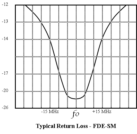
Models FDA-SM & FDE-SM.

The folded dipole models are constructed from heavy duty extruded aluminium tube with a rugged cast aluminium centre clamp. The clamp is attached to the boom with 3 radial bolts to provide a reliable connection. All hardware is stainless steel and to increase the corrosion resistance the aluminium element and boom are silver anodised.
Each dipole is fitted with a RG213 coax tail terminated with an N plug connector, the tail length being 1m from the end of the boom. The folded dipole element is DC grounded. Suitable clamps to use are available. The Pole Mount Clamp (CLPM) for attaching to a wooden pole, or the Cross Clamp (CLCR) to mount to a rigging pipe mounting support.
Specifications
FDA-SM
FDE-SM
Frequency Range (MHz)
75-88
110-180
Bandwidth (MHz)
12
30
Input Impedance (Ohms)
50
Return Loss (dB & VSWR)
>-14dB 1.5:1
Maximum Power (W)
500
Cable Type & Length
RG213, 1 Metre
Connector Type
N Plug
Max Element Length (m)
1.6
0.9
Boom Length (m)
1.5
1.0
Boom Diameter (mm)
48
38
Projected Area (m2)
0.155
0.075
Wind Loading at 150 km/h (N)
170
80
Weight (kg)
4.5
2
VHF YAGIS – PROFESSIONAL SERIES
This comprehensive range of Professional Series Yagi antennas are designed for directional point-to-point applications in the VHF bands. They are designed to be used in the most rugged environments and to withstand harsh weather conditions. They can be used for either vertical or horizontal polarisation. Please specify polarisation when ordering.

The yagis are constructed from extruded Series 6000 silver anodised aluminium with the clamps being cast aluminium and fitted with stainless steel hardware.
All elements are DC grounded.
Models Y2A to Y6A & Y2E to Y6E.
Nominal feed impedance is 50 Ohms with the matching circuit within the sealed driven element. The feed line is typically RG213 coaxial cable and fitted with an N plug connector. Some models are however fitted with a 75 ohm coaxial cable which acts as an impedance transformer. Please note: Do not alter the cable length.
Range 80 – 88 (2-6)
Y2A
Y3A
Y4A
Y6A
Number of elements
2
3
4
6
Frequency range (MHz)
80 – 88
Bandwidth (MHz)
10
5
5
5
Gain (dBd)
3
6
7.5
8.5
Half Power Beamwidth E Plane (deg)
70
65
57
52
Half Power Beamwidth H Plane (deg)
170
100
78
65
Front to back ratio (dB)
10
15
Input impedance (Ohms)
50
Return loss (dB &VSWR)
<-14dB 1.5:1
Connector
N plug
Boom Diameter (mm)
48
Maximum power (W)
350
250
250
250
Cable type (RG)
213
11
11
11
Max element length (m)
1.8
1.9
1.9
1.9
Boom length (m)
1.5
2.0
2.5
3.6
Projected area (m2)
0.23
0.27
0.32
0.41
Wind loading, 150km/hr (N)
250
295
350
450
Weight (kg)
5
6
8
11
Mounting location
Rear
Rear
Rear
Centre
Range 110 – 170 (2-6)
Y2E
Y3E
Y4E
Y6E
Number of elements
2
3
4
6
Frequency range (MHz)
110 – 170
Bandwidth (MHz)
20
10
10
10
Gain (dBd)
3
5
7
8.5
Half Power Beamwidth E Plane (deg)
72
65
55
50
Half Power Beamwidth H Plane (deg)
145
110
74
65
Front to back ratio (dB)
10
15
15
15
Cable type (RG)
213
11
11
11
Input impedance (Ohms)
50
Return loss (dB &VSWR)
<-14dB 1.5:1
Maximum power (W)
250
Connector
N plug
Max element length (m)
1.0
Boom Diameter (mm)
38
Boom length (m)
1.0
1.1
1.6
2.6
Projected area (m2)
0.10
0.12
0.15
0.22
Wind loading, 150km/hr (N)
110
130
165
240
Weight (kg)
2
3
4
6
Mounting location
Rear
Rear
Rear
Centre

VHF FOLDED DIPOLE STACKED ARRAY
The VHF Stacked Array is designed to be used in different configurations, with minimal hardware. These arrays use our Professional Series Folded Dipoles in a stacked configuration to provide added gain.
The folded dipole assembly is mounted to a cast aluminium hub. The centre feed is taken out through the hub and a RG213 coax tail is fed down the centre of the boom and terminated with an N plug connector. The antenna is DC grounded.
FDA3-SA & FDE3-SA
2x Dipoles, 1 x Power Divider (PD-2)
FDA6-SA & FDE6-SA
4x Dipoles, 1 x Power Divider (PD-4)
FDA9-SA & FDE9-SA
8 x Dipoles, 2 x PD-4, 1 x PD-2

Mounting of the boom to a vertical 48mm OD tube can be achieved with a Cross Clamp (CLCR). This allows the dipoles to be spaced from the mounting tube to provide an omnidirectional or offset radiation pattern. The offset pattern provides a further 3 dB gain in the offset direction. This is shown in the radiation pattern on page 18 with “A” being the 1/4 wave offset and “B” the omnidirectional radiation pattern.
Downtilt can be provided by inserting delay lines in the feed system.
Mounting Options: For mounting the Dipoles to a wooden pole use the Pole Mount Clamp (CLPM). For mounting the Dipoles to a vertical 48mm pipe use the Cross Clamp (CLCR).
Optional extras
- Delay lines
- Longer booms
- Separate reflector Element to Clamp on to the boom
- Mounting clamps
Specifications
FDA3-SA
FDA6-SA
Number of dipoles
2
4
Frequency range
75 – 88
Bandwidth (MHz)
12
Omnidirectional gain (dBd)
3
6
Gain with Offset (dBd)
6
9
Half power beamwidth E plane (deg)
27
13
Return loss (dB & VSWR)
<-14dB 1.5:1
Maximum power (W)
750
Cable type
RG213
Connector type
N plug
Boom length (m)
1.5
Boom diameter (mm)
48
Projected area (m2)
0.31
0.62
Wind loading, 150 km/h (N)
340
680
Weight (kg)
9.2
18.4
Specifications
FDE3-SA
FDE6-SA
FDE9-SA
Number of dipoles
2
4
8
Frequency range (MHz)
110 – 180
Bandwidth (MHz)
30
Omnidirectional gain (dBd)
3
6
9
Gain with Offset (dBd)
6
9
12
Half power beamwidth E plane (deg)
27
13
6
Return loss (dB & VSWR)
<-14dB 1.5:1
Maximum power (W)
750
Cable type
RG213
Connector type
N plug
Boom length (m)
1.0
Boom diameter (mm)
38
Projected area (m2)
0.15
0.30
0.60
Wind loading, 150 km/h (N)
165
330
660
Weight (kg)
4.2
8.4
16.8


ISOLATION PROVIDED BY ANTENNA SEPERATION

