
BPF 70/3
The BPF 70/3 is a 3-resonator notch-filter using full-length ¼ λ cavities.
This filter rejects a narrow band of frequencies and passes all others. The filter can be applied both in connection with transmitters and receivers to attenuate interfering signals which cause cross modulation effects. The filter can be employed as a single component or it can act as an integrated part of a complete multi-coupling system.

The BPF 70/3 can be tuned within the complete 406 – 470 MHz band. Careful design and choice of materials ensure reliable operation over a wide temperature range.
The housing is made of extruded aluminium, the chassis of brass, and teflon insulation has been applied in the coaxial cables and in the connectors.
The filter is black vinyl coated to prevent corrosion.
| Electrical | |
|---|---|
| Filter Type | Band-pass filter |
| Frequency | 406 – 470 MHz |
| Max Input Power | 50 W |
| Insertion Loss | < 1.5 dB |
| Impedance | 50 Ohm |
| Reject Attenuation | See curve |
| VSWR | < 1.5:1 |
| Bandwidth | 4 MHz |
| Mechanical | |
|---|---|
| Connection(s) | N type (BNC, TNC, UHF or SMA on request) |
| Dimensions | 225 x 77 x 33 mm (incl. connectors) |
| Weight | 0.55 Kg |


BPF 70/4
The BPF 70/4 is a 4-resonator notch-filter using full-length ¼ λ cavities.
This filter rejects a narrow band of frequencies and passes all others. The filter can be applied both in connection with transmitters and receivers to attenuate interfering signals which cause cross modulation effects. The filter can be employed as a single component or it can act as an integrated part of a complete multi-coupling system.
The BPF 70/4 can be tuned within the complete 380 – 470 MHz band. Careful design and choice of materials ensure reliable operation over a wide temperature range.
The housing is made of extruded aluminium, the chassis of brass, and teflon insulation has been applied in the coaxial cables and in the connectors.
The filter is black vinyl coated to prevent corrosion.
| Electrical | |
|---|---|
| Model | BPF 70/4 |
| Filter Type | Band-pass filter |
| Frequency | 380 – 470 MHz |
| Max Input Power | 50 W |
| Insertion Loss | < 1.5 dB |
| Impedance | 50 Ohm |
| Reject Attenuation | See curve |
| VSWR | < 1.5:1 |
| Bandwidth | 4 MHz – 10 MHz (specify when ordering) |
| Mechanical | |
|---|---|
| Connection(s) | N type (BNC, TNC, UHF or SMA on request) |
| Dimensions | 208 (without connectors) x 104 x 33 mm |
| Weight | 0.69 Kg |


BPF 2/3
The BPF 2/3 is a 3-cavity notchfilter using helical resonators.
This filter rejects a narrow band of frequencies in the 2 m band and passes all others in the range 0 – 430 MHz. The filter can be applied both in connection with transmitters and receivers to attenuate interfering signals causing cross modulation effects. The filter can be employed as a single component or it can function as an integrated part of a complete multicoupling system.

The BPF 2/3 can be tuned within the complete 144 – 175 MHz band. Careful design and choice of materials ensure reliable operation over a wide temperature range.
The housing is made of extruded aluminium, the chassis of passivated steel, and teflon insulation has been applied in the coaxial cables and in the connectors.
The filter is black-vinyl coated to prevent corrosion.
| Electrical | |
|---|---|
| Filter Type | Band-pass filter |
| Frequency | 144 – 175 MHz |
| Max Input Power | 50 W |
| Insertion Loss | < 1.5 dB (typ. 1.0 dB) |
| Impedance | 50 Ohm |
| Reject Attenuation | See curve |
| VSWR | < 1.5:1 |
| Bandwidth | See curve |
| Mechanical | |
|---|---|
| Connection(s) | N type (BNC, TNC, UHF or SMA on request) |
| Dimensions | 160 x 77 x 33 mm |
| Weight | 0.42 Kg |


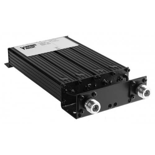
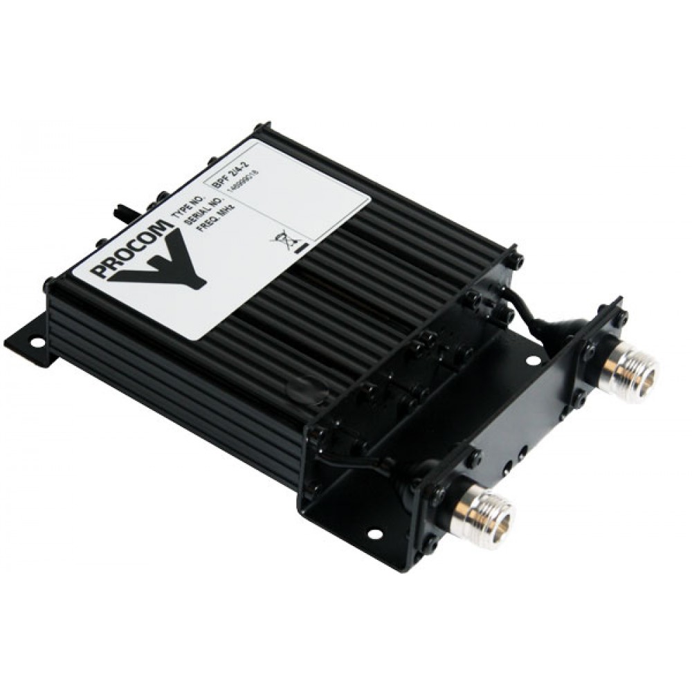
BPF 2/4
The BPF 2/4 is a 4-helical resonator band-pass filter with aperture coupling between the resonators. This filter can be used as a preselector to protect a receiver from interference from transmitters outside the band-pass limits.
The BPF 2/4-C (C = cable) can be installed directly into the PRO-AR4G-N, PRO-AR8G-N and PRO-AR16G-N receiver multicouplers as a preselector. When installed in the output of a transmitter, the BPF 2/4 reduces spurious signals.
The BPF 2/4 is adjustable over the range 144 – 175 MHz. Very compact due to use of helical resonators. Careful choice of materials ensures reliable performance over a wide temperature range.
| Model variations | Frequency |
|---|---|
| BPF 2/4-2 N | 2 MHz |
| BPF 2/4-4 N | 4 MHz |
| BPF 2/4-6 N | 6 MHz |
Extruded aluminium sections, steel racks and coaxial cables and connectors with teflon insulation ensure good mechanical strength. The filter is coated with black vinyl to prevent corrosion.
| Electrical | |
|---|---|
| Filter Type | Band-pass filter |
| Frequency | 144 – 175 MHz |
| Max Input Power | 35 W |
| Insertion Loss | < 1.5 dB (typ. 1.2 dB) |
| Impedance | 50 Ohm |
| Reject Attenuation | See curves |
| VSWR | < 1.5:1 |
| Bandwidth | Can be ordered with 2, 4 or 6 MHz |
| Mechanical | |
|---|---|
| Connection(s) | N type (BNC, TNC, UHF or SMA on request) |
| Dimensions | 165 x 104 x 33 mm |
| Weight | 0.5 Kg |


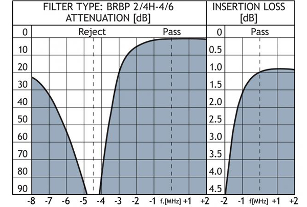
BPBR 2/4 BRBP 2/4
The BPBR 2/4 and the BRBP 2/4 are 4-cavity pass-reject filters, which pass one frequency or frequency band and reject another in immediate vicinity of the pass frequency.
The filters are delivered in two basic models: The BPBR-types have the reject range on the high side of the pass frequency and the BRBP-types have the reject range situated on the low side of the pass frequency.

These filter types can be used to protect a receiver against interference from a nearby transmitter. The filters are tuned to reject the interfering signal. Pass-reject-type filters are applied when the spacing between the utility signal and the interfering signal is so small, that the slope steepness of normal band-pass filters or notch filters are not sufficient enough to provide adequate rejection.
These filters are primarily intended to pass and reject two single frequencies, but the filters can also be tuned to pass and reject several single frequencies or to having a certain pass and reject port bandwidth. In these cases, factory-tuning is recommended.
| Model variations | Spacing | Frequency |
|---|---|---|
| BPBR 2/4 L-4/6 | 4 – 6 MHz | 136 – 154 MHz |
| BRBP 2/4 L-4/6 | 4 – 6 MHz | 136 – 154 MHz |
| BPBR 2/4 L-6/8 | 6 – 8 MHz | 136 – 154 MHz |
| BRBP 2/4 L-6/8 | 6 – 8 MHz | 136 – 154 MHz |
| BPBR 2/4 H-4/6 | 4 – 6 MHz | 152 – 175 MHz |
| BRBP 2/4 H-4/6 | 4 – 6 MHz | 152 – 175 MHz |
| BPBR 2/4 H-6/8 | 6 – 8 MHz | 152 – 175 MHz |
| BRBP 2/4 H-6/8 | 6 – 8 MHz | 152 – 175 MHz |
Both the BPBR 2/4 and the BRBP 2/4 are delivered in a high-band and a low-band version tunable within 136 – 154 and 152 – 175 MHz, respectively. These models are again divided into submodels, each dedicated to work with a certain spacing between the pass frequency and the reject frequency. See “Ordering information” below.
The filter has very small physical dimensions owing to the use of high-Q, temperature compensated helicalresonators.
The housing is made of extruded aluminium, the chassis of passivated steel, and teflon insulation has been applied in the rigid coaxial cables and in the connectors.
The filter is black vinyl coated to prevent corrosion.
| Electrical | |
|---|---|
| Filter Type | Band-pass / Band-reject filters |
| Frequency | 136 – 175 MHz |
| Max Input Power | 50 W |
| Insertion Loss | Single channel tuned < 1.0 dB Multi channel tuned, 1.5 MHz BW <1.2 dB |
| Impedance | 50 Ohm |
| Reject Attenuation | Single channel tuned > 90 dB Multi channel tuned, 1.5 MHz BW > 60 dB |
| VSWR | < 1.5:1 |
| Pass-Reject spacing | 4 – 10 MHz |
| Mechanical | |
|---|---|
| Connection(s) | BNC |
| Dimensions | 210 x 104 x 33 mm |
| Weight | 0.6 Kg |

BPBR 70/3 BRBP 70/3
The BPBR 70/3 and the BRBP 70/3 are 3-cavity pass-reject filters, which pass one frequency or frequency band and reject another in immediate vicinity of the pass frequency.
The filters are delivered in two basic models: The BPBR-types have the reject range on the high side of the pass frequency and the BRBP-types have the reject range situated on the low side of the pass frequency.

These filter types can be used to protect a receiver against interference from a nearby transmitter. The filters are tuned to reject the interfering signal. Pass-reject-type filters are applied when the spacing between the utility signal and the interfering signal is so small, that the slope steepness of normal band-pass filters or notch filters are not sufficient enough to provide adequate rejection.
The filters are primarily intended to pass and reject two single frequencies, but the filters can also be tuned to pass and reject several single frequencies or to having a certain pass and reject port bandwidth. In these cases, factory-tuning is recommended.
| Model variations | Pass / reject spacing |
|---|---|
| Low pass high reject | |
| BPBR 70/3-5/7 N | 5 – 7 MHz |
| BPBR 70/3-7/9 N | 7 – 9 MHz |
| BPBR 70/3-9/13 N | 9 – 13 MHz |
| BPBR 70/3-13/16 N | 13 – 16 MHz |
| Low reject high pass | |
| BRBP 70/3-5/7 N | 5 – 7 MHz |
| BRBP 70/3-7/9 N | 7 – 9 MHz |
| BRBP 70/3-9/13 N | 9 – 13 MHz |
| BRBP 70/3-13/16 N | 13 – 16 MHz |
The BPBR 70/3 and the BRBP 70/3 are both adjustable within the complete 406 – 470 MHz band. Both types can be delivered in four different versions, each dedicated to work with a certain spacing between the pass frequency and the reject frequency. See “Ordering information” below.
The filters use full-length ¼ cavities in a compact, extruded aluminium housing. The chassis is made of passivated steel, and teflon insulation has been applied in the coaxial cables and in the connectors. The filters are black vinyl coated to prevent corrosion.
Careful design and choice of materials ensure reliable operation over a wide temperature range.
| Electrical | |
|---|---|
| Filter Type | Band-pass / Band-reject filters |
| Frequency | 406 – 470 MHz |
| Max Input Power | 50 W |
| Insertion Loss | Single channel tuned < 0.7 dB Multi channel tuned, 2 MHz BW <0.8 dB (at 10 MHz spacing) |
| Impedance | 50 Ohm |
| Reject Attenuation | Single channel tuned > 80 dB Multi channel tuned, 2 MHz BW > 55 dB |
| VSWR | < 1.5:1 |
| Pass-Reject spacing | 5 – 16 MHz |
| Mechanical | |
|---|---|
| Connection(s) | N type (other on request) |
| Dimensions | 225 x 77 x 33 mm |
| Weight | 0.51 Kg |


